displaying posts 851 to 875 of 882

Pages (36): first .. 34 [35] 36

Author Subject: Goldie the track car
prism7guy

Seasoned Pro

Location: DoncastAAAAARGH

Registered: 13 Jan 2008

Posts: 4,637

Status: Offline

Post #851
One other note, had a look at the engine histogram on the DTA earlier to see how long the old engine had spent under various conditions.

Pretty reliable considering it's a 20+ year old engine that was never intended to see boost, yet it spent so long at such high revs. This only indicates the abuse it's had since going to standalone management, before then it had probably similar if not more abuse but without any boost LOL
20190907_154141 by Steve Count, on Flickr

________________________________________

Goldie the track car.
Posted 8th Sep 2019 at 00:32
blandy

Seasoned Pro

Location: Bucks

Registered: 25 Feb 2007

Posts: 2,437

Status: Offline

Post #852
Did you find why cylinder 1 compression was down specifically?

what Camber are you running?

With 3deg and my bc coil overs I have to run a 15mm spacer for the pro races to clear the shocks which is why I’ve stayed with 195’s so watching closely as would like to go to 205’s but not sure it’ll be possible
Posted 8th Sep 2019 at 09:26
prism7guy

Seasoned Pro

Location: DoncastAAAAARGH

Registered: 13 Jan 2008

Posts: 4,637

Status: Offline

Post #853
No I didn't, I've been concentrating on getting the car ready for the ring and don't own a leak down tester yet. I could pull the head off and have a look but the engine is currently sat in the dining room so it's neater to leave as one built up unit for now Laugh

I measured the camber on my not perfectly level drive and it showed 2.8 degrees of negative camber.
How have you achieved your camber?
My wheels are spaced out slightly further than a standard setup as it is as I had to move the wheel out to get the clearance for the brakes. If I remember I'll measure how thick the spacer and the bell are when I'm out stripping it down in a bit.

________________________________________

Goldie the track car.
Posted 8th Sep 2019 at 10:57
blandy

Seasoned Pro

Location: Bucks

Registered: 25 Feb 2007

Posts: 2,437

Status: Offline

Post #854
Tbh id have to find the geo sheet as may well be more like yours and not an exact 3deg as such,
but using baker bm mounts with suspension turrets cut to suit so nothing special as such - rear is on bridgecraft machined arms
Posted 9th Sep 2019 at 16:40
prism7guy

Seasoned Pro

Location: DoncastAAAAARGH

Registered: 13 Jan 2008

Posts: 4,637

Status: Offline

Post #855
I measured the spacer earlier, it's 10mm. I'm pretty sure i machined the bell to 8mm thick so the wheel is basically 18mm from the flange face when bolted up.

I think you asked a while ago about how i'd done the arb, i finally got a clearer picture which hopefully shows how mine is done. It's far from perfect but does the job.
20190826_183942 by Steve Count, on Flickr


I took my KW's off yesterday, the damper with the snapped spring seems to be kaput. Literally no damping in effect if you compress it then pull the shaft as if it was going into droop. Played with it again tonight and it seems to be doing it both ways now. Doh
I decided it was unrealistic to send them off and hope to get them fixed and returned before the trip to Germany, luckily my mate Rob offered for me to borrow his Gaz Golds for a couple of weeks as he wont be using his track car until i'm back.
Few hours later my car now has his dampers fitted Big grin
20190909_181047 by Steve Count, on Flickr

They're running 350lb springs so pretty much the same as my KW's were.
Dropped down to see what sort of ride height it's at i don't think it's a million miles from what the KW's were, i may raise it a little bit tomorrow though to help move the tyre away from the bumper/wing.
Once the ride height is somewhere close i can adjust and set the anti roll bar droplink, then double check the tracking hasnt changed then that's the suspension done.
20190909_183536 by Steve Count, on Flickr

I had a look and these Gaz's are running 8" springs, the spring cups sit above the top of the tyre so there's no chance the tyre could ever touch them. My KW's were the same. I think the Bridgecraft top mounts help in regards to this as they keep the spherical bearing high in the turret so naturally the spring cups need to be higher up on the damper.

Now i need to decide what i'm going to do with the KW's, they've done me proud over the years, i had a quick look around and one place wants ~£100-125 each damper to service & re-valve. So i reckon by the time i've sent them off, got them sorted and bought a pair of new springs i'm going to be a minimum of £300 in. Part of me is now tempted to just put that money towards something a bit more capable. I think i'll get in touch with B.A.D and see how much i'd be looking at for a pair of their 3-ways. Hmm

________________________________________

Goldie the track car.
Posted 9th Sep 2019 at 19:52
prism7guy

Seasoned Pro

Location: DoncastAAAAARGH

Registered: 13 Jan 2008

Posts: 4,637

Status: Offline

Post #856
Update time:

I managed to get to Germany last month. Upon arriving on the Monday i set to swapping over to the Direzza's as soon as i'd unpacked the car. Thats when i was greeted with this:

20190916_162109 by Steve Count, on Flickr

Bugger!
After some team frantic searching around a mate managed to find a pair of rotors in stock at Circuit Supplies Ltd in Leighton Buzzard. The replacements were 315mm overall diameter opposed to my old ones at 310mm, the rest of the dimensions were the same. Fortunately for me my mate was still in the UK until Wednesday so on the Tuesday he went out of his way to pick the new rotors up for me ready to bring over. Absolute legend!

Once he got there with the new rotors he got his friend to have a word with his friend and we got the new rotors turned down to 310mm on that Wednesday evening. Thursday morning soon came round so I set about getting the car ready for some track work as it was TF that evening.

20190919_103004 by Steve Count, on Flickr

20190919_105655 by Steve Count, on Flickr

And a quick comparison between one of my wheels and one of his Laugh

20190919_104805 by Steve Count, on Flickr

After putting a decent few miles on the car during the day to help bed the pads to the discs it was time to head up to the track in the evening. It wasn't a particularly hot evening so i took a mate out for the first lap of the year. After half a lap the coolant had got into the red zone and i was getting some detonation when on boost so i limped round for the rest of the lap then headed back to the apartment.

Once the car was cool enough I drained the coolant and removed the thermostat then filled it with just water ready for the trackday the following day, hoping that without the thermostat fitted there would be minimal flow restriction to the coolant and that it would be enough to keep the temperature sensible.

Finally it was Friday, the day for the trackday. I was one of the first ones into the carpark being the keen bean that I am LOL
As the car park slowly filled up I realised i was in the oldest and cheapest car in there by a country mile Doh LOL

20190920_085622 by Steve Count, on Flickr

20190920_093103 by Steve Count, on Flickr

During the morning i managed to get a few half decent laps in. The Direzza's seem to be a bit more fussy than the old AR-1's in terms of wanting a little heat in them before pushing them hard.
I kept hitting traffic in various spots on most laps causing delays, but one thing was certain, without too many hold ups i managed two 8:03 BTG's back to back according to Harrys lap timer, so the sub8 was definitely within reach!
With this in mind I gave the car 20 mins to cool down whilst i had a drink. I set Harrys lap timer up and stuck my phone in my pocket, hoping the stars would align and i'd get a nice clear lap, before heading to the barrier i went for a tyre warming run up and down the road by the entrance then went out to the track.

I was pretty lucky this lap as I didn't encounter too many hold ups, the trackday documents came out of the helmet hammock and got under my feet which distracted me at one point going 3rd to 5th before dropping back to 4th and chucking the envelope out of the way. Unfortunately because i'd been for the warm up drive on the street I think it messed up the lap timer so i had no way of knowing how quick i'd been. It felt like a quick lap but I knew i'd messed up the gear change and had a couple of other sections where i'd had to scrub a lot of speed off to avoid hitting people when encountering them during a bend.
Here's a pic from said lap Big grin

SCH19L_0771-1 by Steve Count, on Flickr

Having got home i've reviewed said lap and it's a 7:59BTG Hyper
Sub8 video

Unknown to me on the day though i'd still not managed the sub8 which was my main goal so after that lap I let the car cool down and some of the others from the group had now got out of bed and headed up. One of them brought his GoPro and asked if he could attach it to the car for some footage for us both (He is part of a youtube channel and wanted a bit of variety to their usual motorbike content).
With the cameras now setup I went out again, still with the intention of pushing hard. This lap there was a Mercedes AMG GT something or other followed me out of the barriers onto the track. Here is the footage of that lap:

Goldie vs AMG

It was a really fun lap to be fair. At the end of the lap i kept my foot in to get past and give them the thumbs up, just after i did this i experienced detonation again followed by a fair bit of smoke and a car that now sounded a little rough. Doh

20190920_122521 by Steve Count, on Flickr

Game over for goldie this year.

I got the car back to the apartment and started swapping back over to the road wheels, to be greeted by this:

20190920_160352 by Steve Count, on Flickr

Bugger once again! LOL

Long story short, tried to drive it home, sounded rough so got towed by a mate for a bit. That almost ripped the towing eye off and has damaged the bumper in the process. Went back to trying to drive it as far as i could, in the end it got to the stage where it was getting a bit too hot and smokey for comfort in the cabin so i pulled into a motorway service station and noticed the blowby was blasting oil out of the breather filter and filler plug and it was getting on the exhaust manifold so i just called my breakdown and they came to pick it up.
Many weeks later (and a bit of arguing along the way) goldie returned to my house last week.

20191024_152549 by Steve Count, on Flickr

20191024_155602 by Steve Count, on Flickr

Ready for a bit of TLC over winter.

________________________________________

Goldie the track car.
Posted 28th Oct 2019 at 20:08
hovis16

Seasoned Pro

Location: Reading/parts for sale

Registered: 21 Nov 2008

Posts: 4,297

Status: Offline

Post #857
Ooo bit of puff

________________________________________

Ph2 Black GTI 6!

EX black 6 owner
But now a Black caged rallye owner

Hunting for Go faster bits!


SEARCH

click here
Posted 30th Oct 2019 at 15:27
Day666

Seasoned Pro

Location: Bristol

Registered: 20 Apr 2013

Posts: 5,209

Status: Offline

Post #858
GoodLuck Thumbs up
Posted 31st Oct 2019 at 19:04
prism7guy

Seasoned Pro

Location: DoncastAAAAARGH

Registered: 13 Jan 2008

Posts: 4,637

Status: Offline

Post #859
I took the head off the blown engine the other day. I'll let the pictures do the talking.

20191113_184507 by Steve Count, on Flickr

20191113_184518 by Steve Count, on Flickr

20191113_184935 by Steve Count, on Flickr

20191113_185037 by Steve Count, on Flickr

________________________________________

Goldie the track car.
Posted 10th Dec 2019 at 21:41
blandy

Seasoned Pro

Location: Bucks

Registered: 25 Feb 2007

Posts: 2,437

Status: Offline

Post #860
Ouch
Posted 10th Dec 2019 at 21:54
tvrfan007

Seasoned Pro

Location: In the garage

Registered: 29 May 2005

Posts: 3,488

Status: Offline

Post #861
That's not good. What are you pinning it down to?

New engine time...

________________________________________

I'm Si btw Tee hee

Night Blue VW Golf GTD
Bianca LBSC Rallye - Track/Road Slag Project Thread
Sparkling Silver Mini Cooper D - Super Dooper Superman - (The other half's wheels)
Posted 12th Dec 2019 at 08:35
prism7guy

Seasoned Pro

Location: DoncastAAAAARGH

Registered: 13 Jan 2008

Posts: 4,637

Status: Offline

Post #862
Ouch indeed!

I'm pinning it down to a few things that worked together against me, the biggest problem being me and my stupidity of refusing to back off the throttle the second i knew something wasn't right.

The engine was running hotter than usual (around 100c coolant even with the thermostat completely removed) which won't have helped, and the fuel I was using was only 98 octane rather than the 99 it was mapped on. I only noticed the octane rating was down the night before the trackday after i'd brimmed the tank Doh

I'm in the process of sorting a temporary new engine for it now, that should be sorted during the christmas break provided i don't hit any snags but yes, it's about time i stop messing around and build a proper lump for it! I've been slowly collecting parts ready for such an engine so it's not a million miles off being sorted.

________________________________________

Goldie the track car.
Posted 12th Dec 2019 at 16:42
hovis16

Seasoned Pro

Location: Reading/parts for sale

Registered: 21 Nov 2008

Posts: 4,297

Status: Offline

Post #863
You could see the moment it went in the video. Thrashing it mate Wink

________________________________________

Ph2 Black GTI 6!

EX black 6 owner
But now a Black caged rallye owner

Hunting for Go faster bits!


SEARCH

click here
Posted 13th Dec 2019 at 20:34
Day666

Seasoned Pro

Location: Bristol

Registered: 20 Apr 2013

Posts: 5,209

Status: Offline

Post #864
Good luck ..gutted for you Thumbs down
Posted 17th Dec 2019 at 13:06
prism7guy

Seasoned Pro

Location: DoncastAAAAARGH

Registered: 13 Jan 2008

Posts: 4,637

Status: Offline

Post #865
Had a busy christmas messing about with the car.

I got the engine out which let go at the Nordschleife and took it apart to assess the damage.

20191224_122800 by Steve Count, on Flickr

20191224_124439 by Steve Count, on Flickr

20191224_140653 by Steve Count, on Flickr
Shock Laugh

I don't think i took any more pictures of the block but i suspect it's a complete write off, the scoring was excessive and i'm not sure that even boring it out to 87mm would clean it all up.

________________________________________

Goldie the track car.
Posted 10th Jan 2020 at 23:34
prism7guy

Seasoned Pro

Location: DoncastAAAAARGH

Registered: 13 Jan 2008

Posts: 4,637

Status: Offline

Post #866
Next up i decided to strip the engine which i hurt at Cadwell earlier in 2019, where cylinders 1&4 were both down on compression.

Cylinder 1:

20191206_165813 by Steve Count, on Flickr

20191208_182434 by Steve Count, on Flickr

20191208_182540 by Steve Count, on Flickr

Cylinder 2:

20191206_165827 by Steve Count, on Flickr

Cylinder 3:

20191206_165841 by Steve Count, on Flickr

Cylinder 4:

20191206_165739 by Steve Count, on Flickr

20191208_182137 by Steve Count, on Flickr

20191208_182021 by Steve Count, on Flickr

As you can see there's evidence of detonation and i've murdered the top piston rings on both cylinders 1&4. The bores for each have seen better days as a result and this helps explain the lack of compression i was able to achieve.

Since these pistons have been pocketed to allow more valve clearance and the detonation damage to the pistons themselves doesn't look too bad i've decided they're re-usable. Obviously it's not ideal but as it stands i simply need an engine that starts and runs on a fairly tight budget. The long term plan for the new engine is to go into the 205 shell which i've got sat on the drive which will be fitted with a set of bike throttle bodies and maybe some mild cams (hence why i wanted to use the pocketed pistons), short term i just need goldie to start and drive as i intend to move house in the next few months.

________________________________________

Goldie the track car.
Posted 10th Jan 2020 at 23:32
prism7guy

Seasoned Pro

Location: DoncastAAAAARGH

Registered: 13 Jan 2008

Posts: 4,637

Status: Offline

Post #867
Whilst all the bottom end stripping was going off i was also sorting out a new cylinder head to use. The one which was on the Cadwell engine was the victim of an extensive skim a couple of years ago so that was out of the question. This left me with the head which was on the engine which let go in Germany.
With the head off i measured it and it was 137mm so it has never had a skim in the past. Nice.

I used a straight edge over the head and it looked pretty true. Upon removing the valves it was apparent that the exhaust valves and their seats had seen better days.

20191129_142423 by Steve Count, on Flickr

At this point i decided it was time to take the head down to the local machine shop and get a light skim along with having 16 new valve guides, the valves and seats re-cut and a clean.
A few weeks later it was ready for collection.

20191213_170352 by Steve Count, on Flickr

Re-assembling a head is pretty straight forward just time consuming. First off i thoroughly cleaned the head with clean water then copious amounts of brake cleaner and blasting it with the air line. Once i was happy it had no swarf or crap still hidden away I put the spring seats back down over the valve guides

20200102_175620 by Steve Count, on Flickr

Next up was new valve stem oil seals. A while ago i bought a tool to make this job easier. It's not necessary but makes the job a bit quicker and easier. In the past i've used a deep socket the right size to tap them home over the valve guides.

20200102_172020 by Steve Count, on Flickr

20200102_172059 by Steve Count, on Flickr

20200102_181308 by Steve Count, on Flickr

Next up was to refit the valves, both valve springs and the retainer caps, then compress these using a valve spring compressor.

20200103_190739 by Steve Count, on Flickr

The final stage is to fit both halves of the retainers. These are fiddly to say the least but having read tips on here and previous builds i've found the easiest way to do these is to dab some grease on them, then use a magnetised screwdriver to reach down and put them in place on the valve stem. Once you are happy they are in the right place push them a bit harder to the valve stem and the grease should 'stick' them in place. Repeat for the other half. Once both are in place the spring compressor can be undone and that valve is complete.

20200103_190727 by Steve Count, on Flickr

20200103_191142 by Steve Count, on Flickr

20200103_193830 by Steve Count, on Flickr

________________________________________

Goldie the track car.
Posted 10th Jan 2020 at 23:56
hovis16

Seasoned Pro

Location: Reading/parts for sale

Registered: 21 Nov 2008

Posts: 4,297

Status: Offline

Post #868
I do enjoy a head rebuild, much nicer than the bottom end. Got a spare head I'm thinking of doing soon as well

________________________________________

Ph2 Black GTI 6!

EX black 6 owner
But now a Black caged rallye owner

Hunting for Go faster bits!


SEARCH

click here
Posted 11th Jan 2020 at 20:20
blandy

Seasoned Pro

Location: Bucks

Registered: 25 Feb 2007

Posts: 2,437

Status: Offline

Post #869
Great read as always

That poor piston though lol
Posted 11th Jan 2020 at 21:40
prism7guy

Seasoned Pro

Location: DoncastAAAAARGH

Registered: 13 Jan 2008

Posts: 4,637

Status: Offline

Post #870
hovis16 wrote:
I do enjoy a head rebuild, much nicer than the bottom end. Got a spare head I'm thinking of doing soon as well


I find both enjoyable when i'm not in a rush, both are very time consuming though.

blandy wrote:
Great read as always

That poor piston though lol


Thanks mate Thumbs up
Yeah, i must have put the poor thing through hell! Laugh

________________________________________

Goldie the track car.
Posted 12th Jan 2020 at 19:15
prism7guy

Seasoned Pro

Location: DoncastAAAAARGH

Registered: 13 Jan 2008

Posts: 4,637

Status: Offline

Post #871
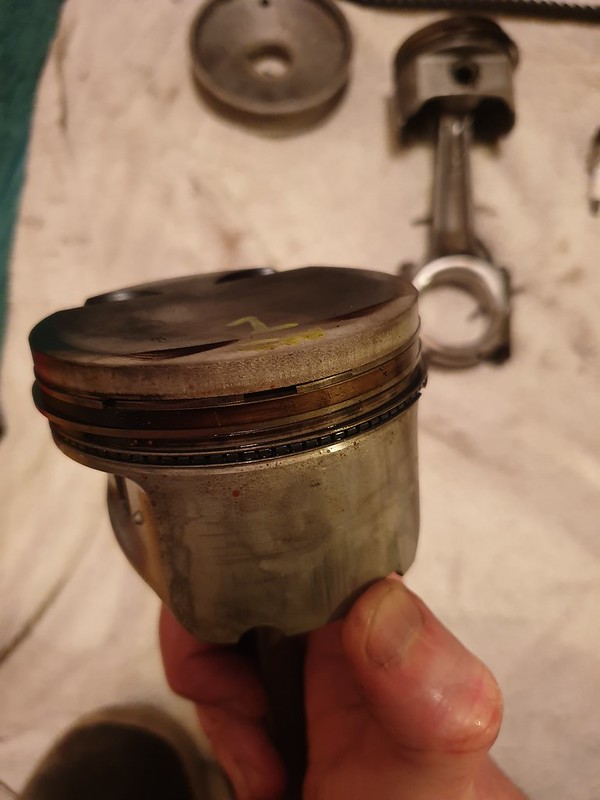
I dragged a spare bottom end out of the shed and set to work stripping it down.

20191215_130848 by Steve Count, on Flickr

After a couple of hours attacking it with wire wheels

20191230_123410 by Steve Count, on Flickr

After a couple of coats of red oxide primer

20191230_132041 by Steve Count, on Flickr

Three coats of halfords red engine enamel

20191231_144240 by Steve Count, on Flickr

Mounted the gearbox up and marked where paint needed removing to ensure the bellhousing sat flush with the block then took the paint away with a wire wheel where needed

20200102_121704 by Steve Count, on Flickr

Bought myself a honing tool for christmas and set about honing the bores, used loads of wd40 to keep things lubricated.

20200102_124403 by Steve Count, on Flickr

The only picture i seem to have got of the bores, this was after a few passes just to see how fast i needed the speed and how quick i needed to go up and down in the bores to get a decent cross-hatch. I removed the oil spray bars so the hone could go to the bottom of each bore. I masked as much as i could of the main journals and the oil spray bar oil feed holes to stop any crap getting into the oil galleries.
20200102_130220 by Steve Count, on Flickr

After honing I cleaned everything down thoroughly with hot water and washing up liquid, then blasted everything with the hose pipe. Next was blasting it with the air line, then going over everything again with copious amounts of brake cleaner. I kept wiping the bores with fresh blue rag soaked in brake cleaner until they were coming out with no evidence of any honing debris. Next a quick spray over with wd40 to stop any rust forming.
The oil galleries were blasted with a few cans of brake cleaner to make sure there was nothing bad in them. Likewise the crank had all the oil ways blasted until the brake cleaner was coming out clear.

Next i refitted the oil spray bars

20200102_164627 by Steve Count, on Flickr

I bought 4 new sets of Mahle piston rings. The documents didn't specify anything for what the ring gap should be so I emailed them. They just said the rings come pre-gapped and didn't acknowledge any need for bigger gaps with the engine being boosted.

I numbered the piston ring packs 1-4, and kept each set of rings in the relevant pack and assigned them to each cylinder. I inserted each ring into its corresponding bore and used a piston to push the ring down the bore nice and square then used feeler gauges to measure the ring gaps. I did this for the top and middle rings and noted the gaps.

20200102_171448 by Steve Count, on Flickr

20200102_165906 by Steve Count, on Flickr

20200102_165615 by Steve Count, on Flickr

After i'd done them all they all seemed to be pretty much the same so i went ahead and fitted them to the pistons.

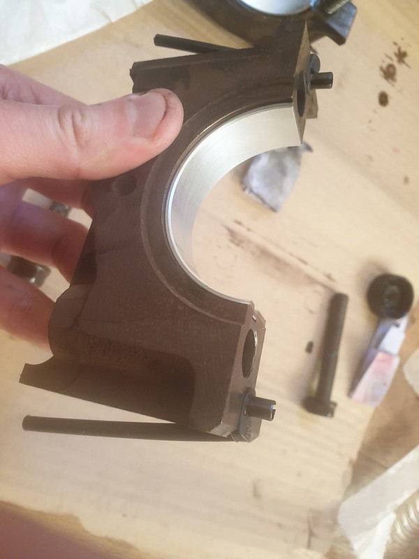
Next up i made sure all the main journals were clean and fitted the new main shells to the block and dropped in the crank.
I know it's not a perfect way of measuring anything but it's good as an indication of clearance so i went ahead and got the plastigauge out and measured all the main journal clearances. Torqued the caps down to the recommended specs.

20200103_133535 by Steve Count, on Flickr

20200103_133551 by Steve Count, on Flickr

20200103_134942 by Steve Count, on Flickr

20200103_135009 by Steve Count, on Flickr

The plastigauge readings were all pretty similar and from memory they are within spec of what the clearance should be so I cleaned all the plastigauge off, removed the crank and went ahead with coating the bearings with graphogen assembly compound. I then refitted all the main caps and torqued them all back down to spec, not forgetting to fit the thrust bearings.
Now that i could rotate the crank I checked the end float. When putting #1 main cap in i fitted new hockey stick seals and added a thin bead of sealant just incase the rubber didnt create a perfect seal.

20200103_141046 by Steve Count, on Flickr

20200103_141144 by Steve Count, on Flickr

20200103_142239 by Steve Count, on Flickr

20200103_135912 by Steve Count, on Flickr

20200103_140754 by Steve Count, on Flickr

20200103_140757 by Steve Count, on Flickr

Thats 0.14mm of end float, which is between the tolerances i found of 0.07 - 0.27mm online.

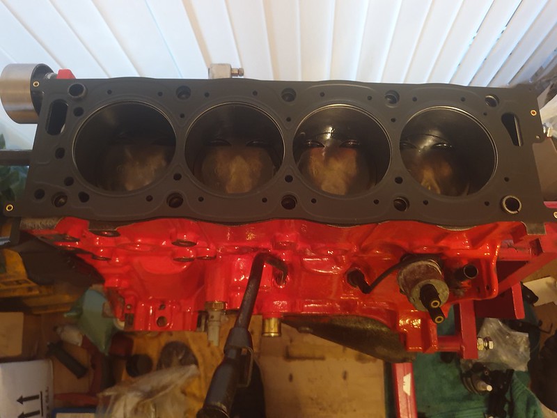
Next job was to fit the pistons and rods. Firstly i went over each bore again with brake cleaner on blue roll then I coated all the bores and piston ring compressor with fresh engine oil to help keep everything lubricated, and gave the skirts of the pistons a wipe over with engine oil too.

20200104_122553 by Steve Count, on Flickr

Once again I used plastigauge to get an idea of clearance for each big end, torquing the caps down as they should be.

20200104_112705 by Steve Count, on Flickr

20200104_120536 by Steve Count, on Flickr

They were all pretty much the same and once again they were within tolerance from memory.
The journals don't look too pretty in the pictures but i ran a fingernail over each one and couldnt feel anything. I also had a micrometer on all the big end journals and all measured mid-tolerance.
After plastigauging i cleaned all the plastigauge off, coated the moving faces with graphogen then torqued the caps down.
The crank could be rotated by hand at this point which is reassuring that nothing is binding. I probably should have mentioned earlier but each time i torqued down a main cap i'd try and give the crank a turn to make sure it wasnt binding, likewise with each big end.

Next up i fitted the windage tray

20200104_130755 by Steve Count, on Flickr

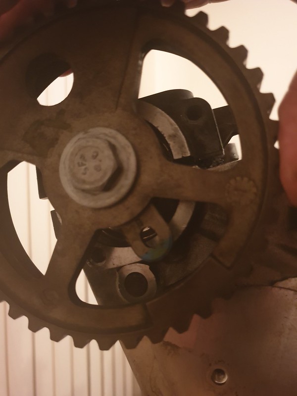
The oil pump sprocket that was used previously on the engine was the old design where the sprocket relies purely on the pulley bolt being tight enough to clamp it and stop it spinning. I then raided one of my other engines for the newer design sprocket where the sprocket and spacer part are one piece which then means the woodruff key positively drives it ensuring it is locked to the crank regardless of how tight the crank pulley bolt is.

20200104_132035 by Steve Count, on Flickr

20200104_132155 by Steve Count, on Flickr

Oil pump and chain fitted. Don't forget the 'L' shim. Loctite used on all the bolts.

20200104_133433 by Steve Count, on Flickr

20200104_133741 by Steve Count, on Flickr

Reinserted the dipstick tube and bolted it in place on the oil pump

20200104_133758 by Steve Count, on Flickr

I'd bought the Payen gasket kit for the rebuild, and also bought new crank seals. New seal fitted to the engine end plate after cleaning it and applying a bead of sealant to the mating surface.

20200102_171830 by Steve Count, on Flickr

20200104_135810 by Steve Count, on Flickr

Next up i fitted the cambelt pulley and billet crank pulley and spun the crank so the pulley hole lined up with the locking point on the engine making sure the pistons were all mid-stoke. I'd also fitted the water pump along with a new gasket and both the tensioner pulley and idler pulley for the cambelt. Also the two dowels to locate the head in the correct position. Also cleaned out the sump and fitted it with a bead of sealant around the mating faces. Not shown in these pictures but done at this stage was locking the crank in place using an 8mm drill blank.

20200104_150609 by Steve Count, on Flickr

20200104_160314 by Steve Count, on Flickr

Placed the new head gasket in place, ensuring the dowels held it in place.

20200104_160444 by Steve Count, on Flickr

Carefully put the head back on being careful to line up the dowels and not scrape/damage the mating face.

20200104_160734 by Steve Count, on Flickr

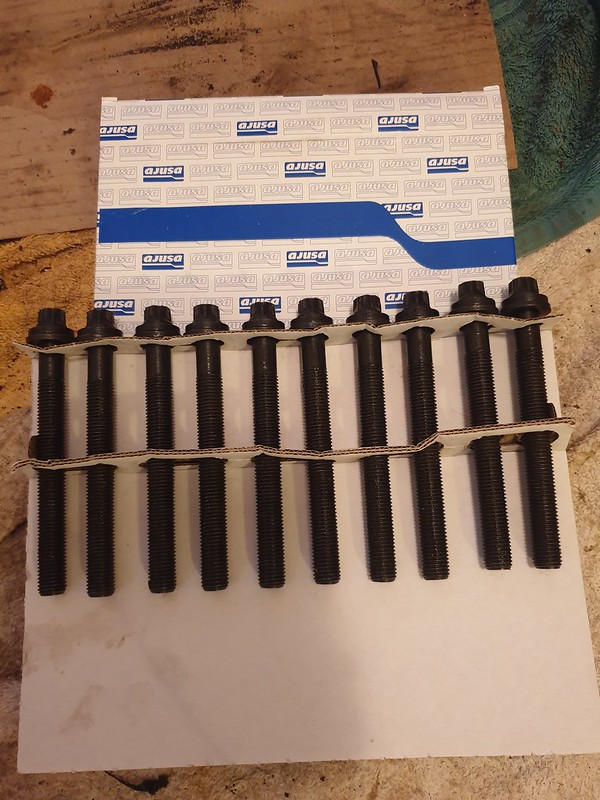
Next up I fitted new head bolts and torqued them down in the correct sequence to the torque rating in each stage. The final stage is 160*, which is quite hard work doing it on your own when the engine stand is on wheels and wants to spin Doh Laugh
I managed it in the end by standing on the stand base.

20200104_160858 by Steve Count, on Flickr

Next up was to apply graphogen to the hydraulic lifters, ensuring each one went in the bore it came out of originally. I do this by using seperate food bags for each one and putting that bag inside another food bag with a piece of card labelled to identify where it should live. i.e. 'In1', 'In2', 'Ex1', 'Ex2' etc I put the various other bits of the valvetrain in bags like this too.

20200104_174104 by Steve Count, on Flickr

Next up I made sure the exhaust cam was clean. I fitted the pulley to the end and did the bolt up finger tight. I applied sealant to the mating face where the cam carrier meets the head, applied graphogen to the lobes and all the journals, then laid the camshaft in the journals so that the locking hole was slightly anti-clockwise to the locking hole on the head.

20200104_180801 by Steve Count, on Flickr

Next i then tighten down the cam carrier capscrews, the final sequence spiraling out from the centre much like doing the head bolts.
With the carrier clamped down i then insert the new seal, using a bit of tube to ensure it's located flush and square.

20200104_181640 by Steve Count, on Flickr

20200104_181653 by Steve Count, on Flickr

20200104_181736 by Steve Count, on Flickr

Don't forget the oil spray bar

20200104_182526 by Steve Count, on Flickr

Do exactly the same for the inlet cam side

20200104_190453 by Steve Count, on Flickr

Pulleys back off to fit the cambelt cover

20200104_191444 by Steve Count, on Flickr

Pulleys back on, now you want to use an 18mm spanner on the camshaft pulley bolts to carefully rotate the camshaft clockwise whilst you use a 6mm drill blank to lock the camshaft in place with the relevant hole in the head. Once each cam has been locked in place carefully crack off the bolts so the pulley can rotate on the camshafts, rotate them as far clockwise as possible by hand, then place the cambelt round the bottom pulley, round the idler pulley, over the inlet cam pulley, round the exhaust cam pulley, round the tensioner pulley then water pump and back round the crank pulley. The crank pulley should be locked in place with an 8mm drill blank.
A better description of this process can be found in the FAQ guide on this forum along with more pictures along the way.
Once the belt is in place use the tensioner to set the belt tension and nip it in place. Tighten the cam pulley bolts and remove all three locking pins. Rotate the crankshaft clockwise carefully multiple times then try fitting the drill blanks back into all 3 locking holes. If they line up then great, if not then you've gone wrong somewhere. If everything is as it should be torque everything to the correct torque and make sure you applied loctite to the bolts so they wont rattle loose in the future.

20200104_193951 by Steve Count, on Flickr

20200104_201350 by Steve Count, on Flickr

This is as far as i've got so far, i'm still waiting for new flywheel bolts and the m20x1.5 oil filter tube to come in at the local dealers.

________________________________________

Goldie the track car.
Posted 12th Jan 2020 at 20:33
hovis16

Seasoned Pro

Location: Reading/parts for sale

Registered: 21 Nov 2008

Posts: 4,297

Status: Offline

Post #872
Ah fun times doing this in my garage with Paul. Need to build another, enjoy the bed in procedure hopefully you have nice dead road nearby

________________________________________

Ph2 Black GTI 6!

EX black 6 owner
But now a Black caged rallye owner

Hunting for Go faster bits!


SEARCH

click here
Posted 12th Jan 2020 at 22:21
stef306

Regular

Location: lyme regis

Registered: 20 Sep 2009

Posts: 201

Status: Offline

Post #873
did you go for a bigger ring gap being with boost? i was advised by sandy to do this on my new engine.

________________________________________

1990 205 gti6 supercharged
Posted 16th Jan 2020 at 21:40
prism7guy

Seasoned Pro

Location: DoncastAAAAARGH

Registered: 13 Jan 2008

Posts: 4,637

Status: Offline

Post #874
hovis16 wrote:
Ah fun times doing this in my garage with Paul. Need to build another, enjoy the bed in procedure hopefully you have nice dead road nearby


Sod working in the garage in the cold, i brought it into the house Laugh Plenty of decent quiet roads round me which i'll be utilising once it goes back together.

stef306 wrote:
did you go for a bigger ring gap being with boost? i was advised by sandy to do this on my new engine.


I left the ring gaps as they came from Mahle. They wouldn't give me any numbers for gaps even though i specified it was going in a boosted engine. I'd read a few measurements from various other people on the internet on various other engines which are all around the ball park of what these measured. The top rings were all between 0.4-0.45mm gap, and the middle ones were all between 0.45-0.5mm (three were pretty much bang on 0.45mm).

Couple of reasons i left them as they were, one is that the engine will probably not be seeing any action on track so they shouldn't get too hot, and the second reason is the engine will be coming out and getting throttle bodies in the near future used on a road car, so once again they'll have a relatively easy life and not need the extra gap.

The bores in the new block were all also worn slightly from it's previous life, i didn't bother getting the bore mic on them to see what they were but there was a step noticeable under a nail where the top of the stroke was so the bores are obviously worn slightly and therefore that will have helped open up the ring gaps slightly too.

________________________________________

Goldie the track car.
Posted 16th Jan 2020 at 22:45
hovis16

Seasoned Pro

Location: Reading/parts for sale

Registered: 21 Nov 2008

Posts: 4,297

Status: Offline

Post #875
Lol throttle bodies, road, easy life I think not.

________________________________________

Ph2 Black GTI 6!

EX black 6 owner
But now a Black caged rallye owner

Hunting for Go faster bits!


SEARCH

click here
Posted 18th Jan 2020 at 18:03

Pages (36): first .. 34 [35] 36

All times are GMT. The time is now 01:16

The Peugeot GTi-6 & Rallye Owners Club - ©2024 all rights reserved.

Please Note: The views and opinions found herein are those of individuals, and not of The Peugeot 306 GTi-6 & Rallye Owners Club or any individuals involved.
No responsibility is taken or assumed for any comments or statements made on, or in relation to, this website. Please see our updated privacy policy.