Post #682
Time for a quick update. The car is now back on the road.
First off i decided to try and fix the two knackered superchargers.
So i took them apart and used a gear puller to remove the gears from the shafts.
 IMG_6750
 by
Steve Count, on Flickr
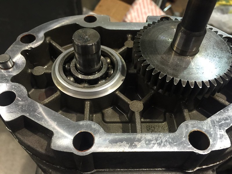
It's only the inner race of this bearing and the gear being pressed on that secures the rotors laterally, which should stop the rotors from moving down and hitting the inlet end of the housing. (The thing i'm having problems with)
There is only around 6.5mm of the rotor shaft that lives in the inner race, and the interference fit with the bearing is much lighter than it is with the gear, which i guess is to be expected.
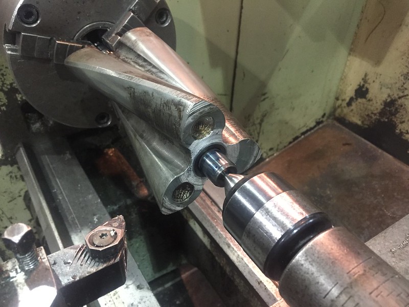
Anyway, i stuck the rotors in the lathe and cleaned up the end of the rotors, i took 0.2mm off each one. Not ideal in terms of supercharger efficiency, but hopefully enough to stop myself having any more incidents in the future.
 IMG_6752
 by
Steve Count, on Flickr
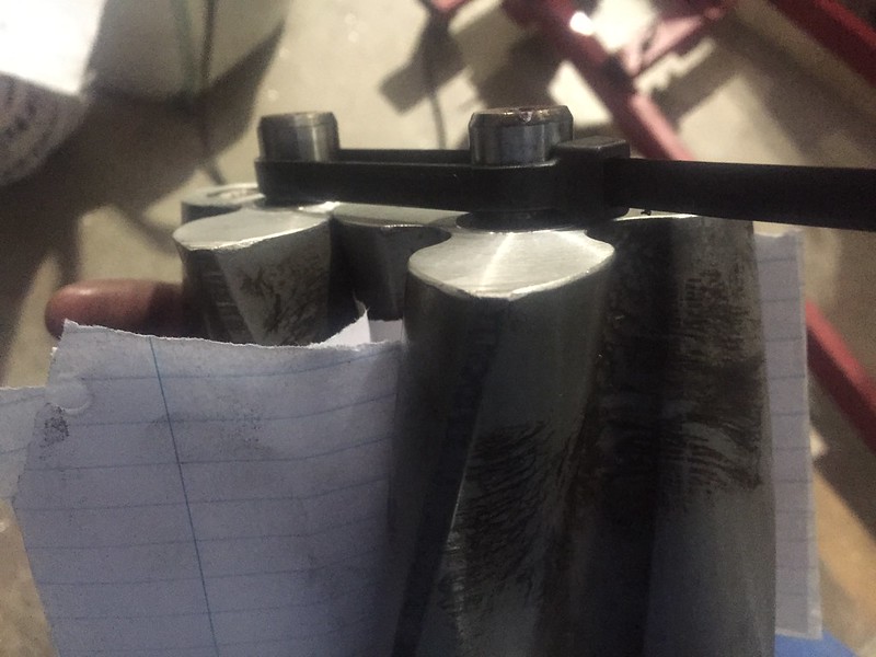
Once the rotors had been cleaned up i removed the sharp edges with a file and made a start rebuilding the rotor pack.
Couple of sheets of paper between the rotors, with the shafts held together as tight as a zip tie would hold them before pressing the rotors into the bearings. This should hold the rotors an equal distance apart which is what is needed for timing them when i press the gears back on in a bit.
 IMG_6760
 by
Steve Count, on Flickr
I then pressed the rotor shafts into the bearings, leaving around 0.25mm between the rotor face and the face of the rotor pack plate.
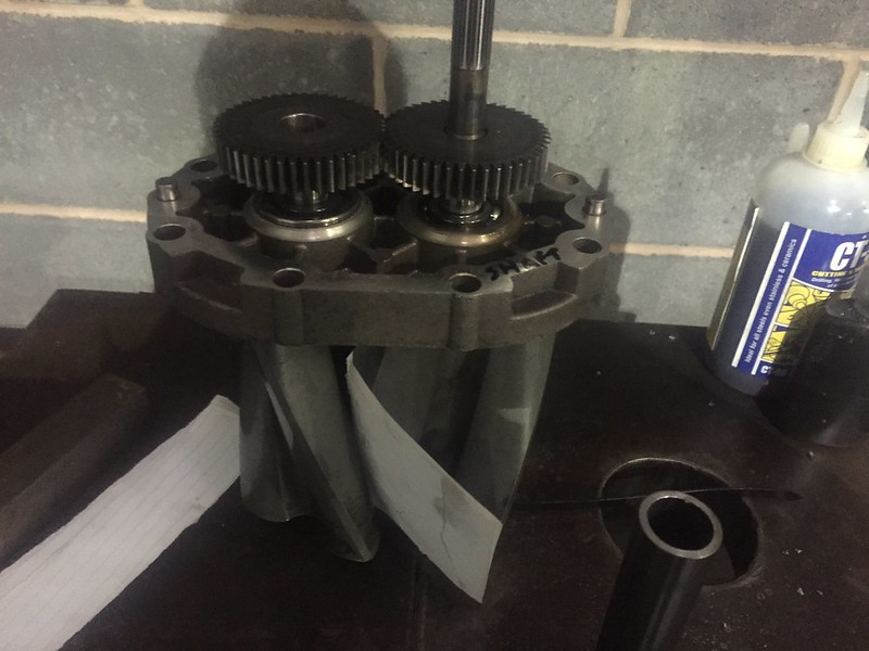
Next i placed both gears on the shafts, and pressed each gear on a little at a time then did a little on the next one, as pressing all the way on in one go would be too much and could throw the timing out (the teeth would come out of mesh).
 IMG_6761
 by
Steve Count, on Flickr
I pressed the gears on so that they butted up against the inner race of the bearings, and made sure there was still 0.25mm of clearance for the rotors.
That's the rotor pack bit done.
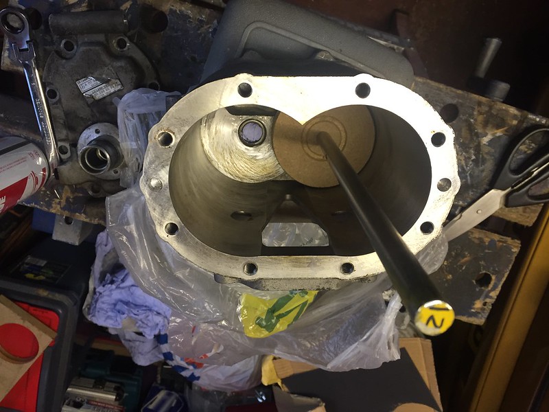
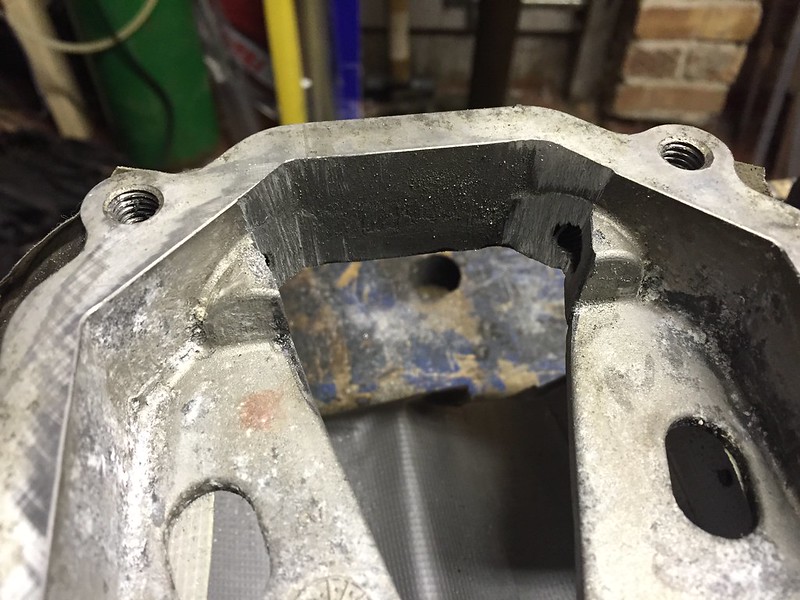
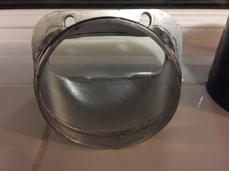
Next up i had to sort out the inner face at the inlet end of the housing.
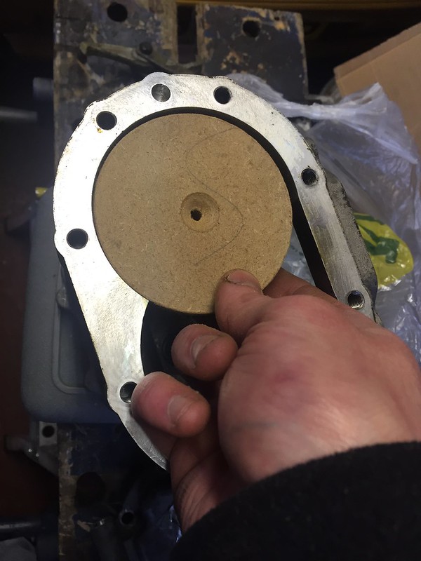
I filled the needle roller bearings with kitchen roll to try and stop any swarf or contaminants getting in, then devised a make-do tool for cleaning up the face.
~18mm thick MDF cut to size with a hole saw (Cant remember the diameter off hand)
 IMG_6763
 by
Steve Count, on Flickr
Spray adhesived a bit of wet and dry to one side.
 IMG_6764
 by
Steve Count, on Flickr
Used a capscrew into a bit of round bar that i'd drilled and tapped, and stuck it in the drill.
 IMG_6768
 by
Steve Count, on Flickr
 IMG_6769
 by
Steve Count, on Flickr
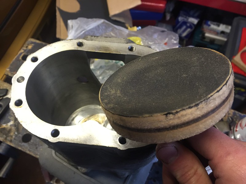
Before:
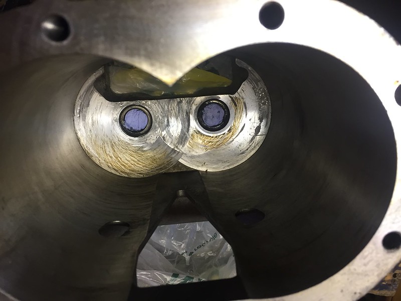 IMG_6767
 by
Steve Count, on Flickr
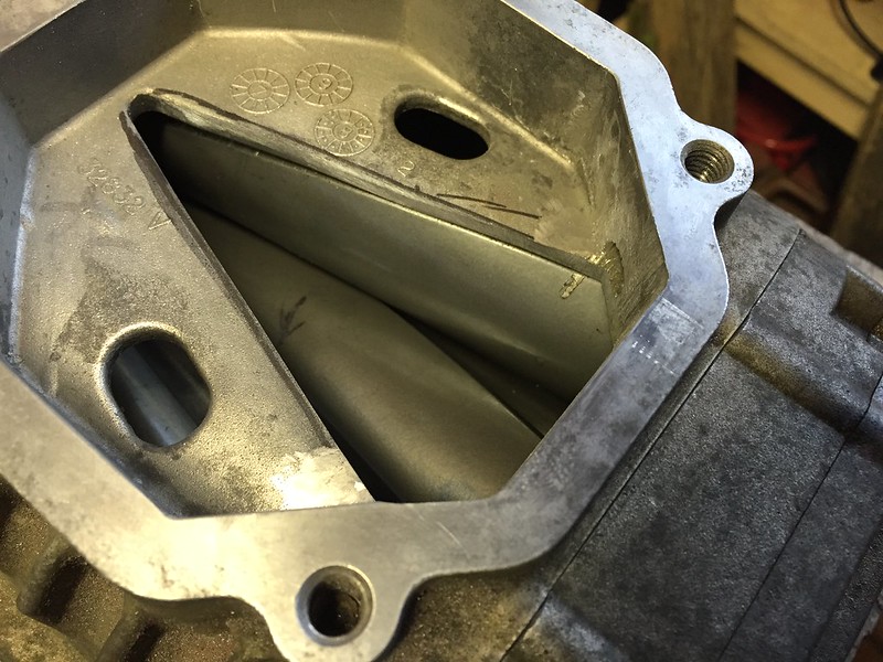
After:
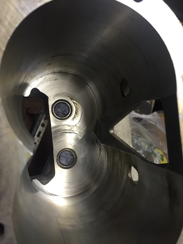 IMG_6771
 by
Steve Count, on Flickr
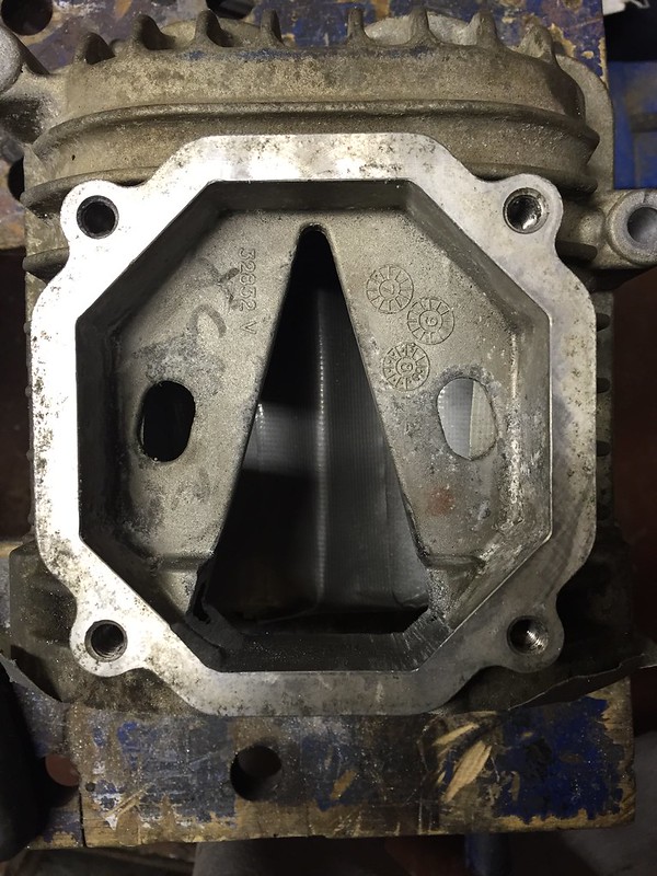
It took several attempts with wet and dry, but eventually i removed all the high spots.
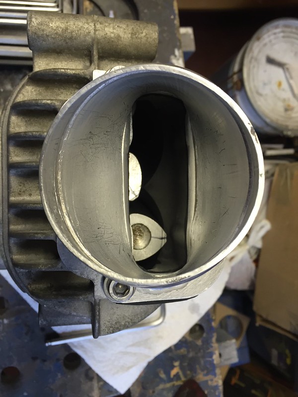
I did the above process on the first two superchargers. I also decided to have a go at porting one of them, trying to improve the outlet slightly.
Couple of pics of that:
 IMG_6785
 by
Steve Count, on Flickr
 IMG_6786
 by
Steve Count, on Flickr
 IMG_6788
 by
Steve Count, on Flickr
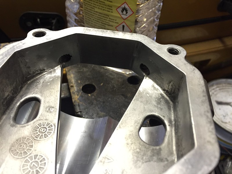 IMG_6790
 by
Steve Count, on Flickr
I tried cleaning out the roller bearings in the ported housing as i suspected a little swarf may have got in somehow, i just filled them with white spirits several times to loosen the gease, then eventually when that was gone i swilled them out a few times with acetone, then replaced the grease with some molykote 44 (from memory). It's what i read should be used on various forums online.
I rebuilt that charger but it doesn't spin freely like the others, so i suspect the timing is either out, or the bearings still have some swarf in them.
Having done some research it seems that the bearings in the rotor pack are not supposed to be replaced (the rotor plate is formed round the bearings to hold them in place). I've thought of a way around this to hold new bearings in, but i'd need to get some plate laser cut for that so that's a job for another day rather than messing around with minimum order charges etc.
The needle roller bearings are debatable whether they're replaceable, some people have got them out without issues, whereas others said they deformed the housing getting them out. Plus these ones were custom sized by eaton and made by INA only, they are a bit tricky to get hold of without paying more than i'm willing to pay to say there's no guarantee they'll be replaceable easily.
I then finished off rebuilding the superchargers, and put 110ml of fresh oil in them all.
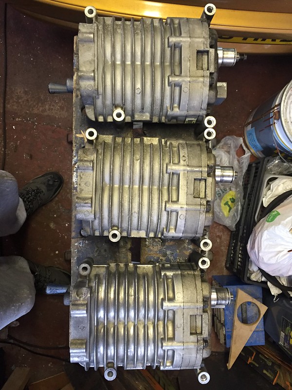 IMG_6794
 by
Steve Count, on Flickr
The latest one didn't show any signs of damage/wear and the clearance measured fine with feeler gauges, so that was reassembled as-is and just had fresh oil put in.
Another gripe is how overpriced supercharger oil seems to be, it's around £20 for ~150ml.
I spoke to opie oils and they said they know of a few people using 5W40 engine oil without issues in superchargers, so i bought a 1 litre bottle of Fuchs Pro S for this job. It seems to be working alright so far.
Whilst i was messing around porting, i decided to spend a bit more time cleaning up my inlet manifold for the 'charger. Made it much smoother now so it should flow a little better.
 IMG_6793
 by
Steve Count, on Flickr
 IMG_6795
 by
Steve Count, on Flickr
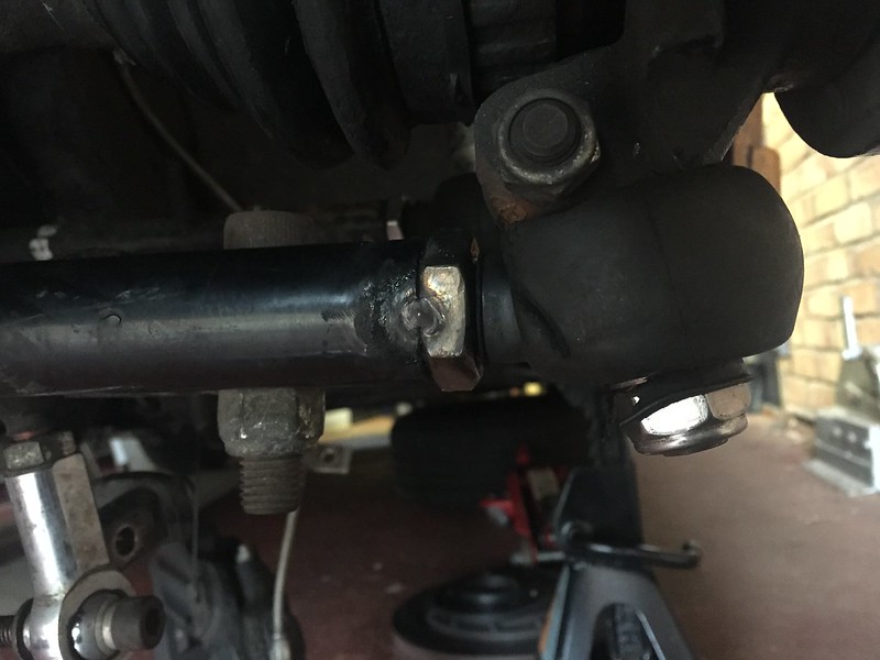
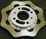
Next job was to sort the auto tensioner. They aren't made to suit an 8 rib belt, so once again i had to get the files out and spend ages slowly removing aluminium.


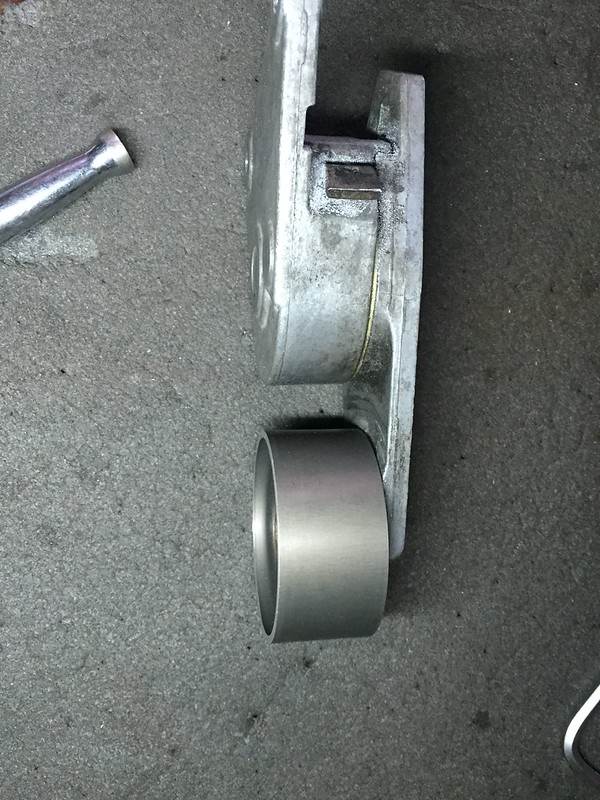 IMG_6775
 by
Steve Count, on Flickr
That's now fitted and seems to work fine.
Next job was to make an expansion bottle, as my header tank would lose coolant when it expanded, then obviously it would lower the level when the engine cooled back down.
For this, i'd pretty much ran out of money so went to the supermarket in search of a bottle i could adapt. The result:
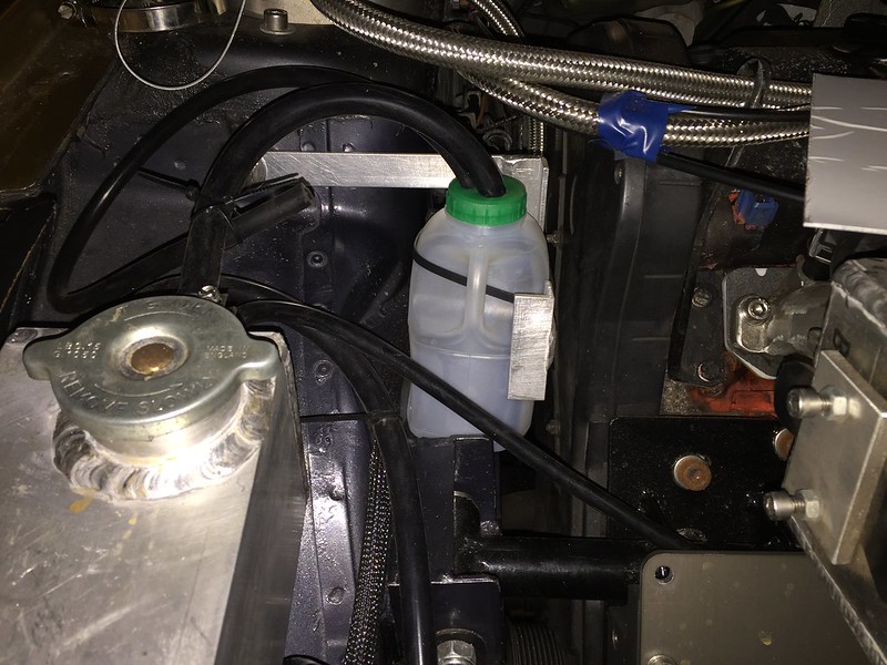 IMG_6783
 by
Steve Count, on Flickr

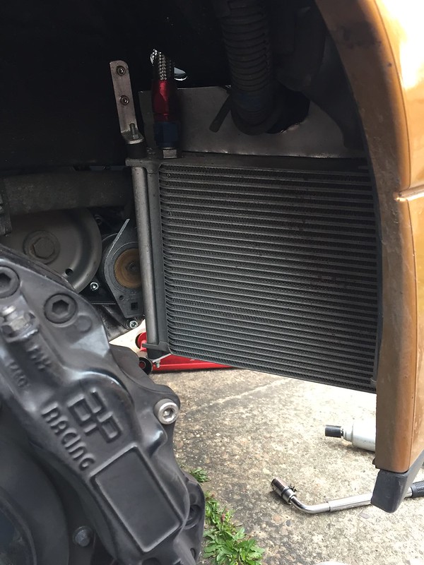
Another thing on my list of things to improve was the oil temperature. It was reaching 135c+ at blyton last year, far from ideal!
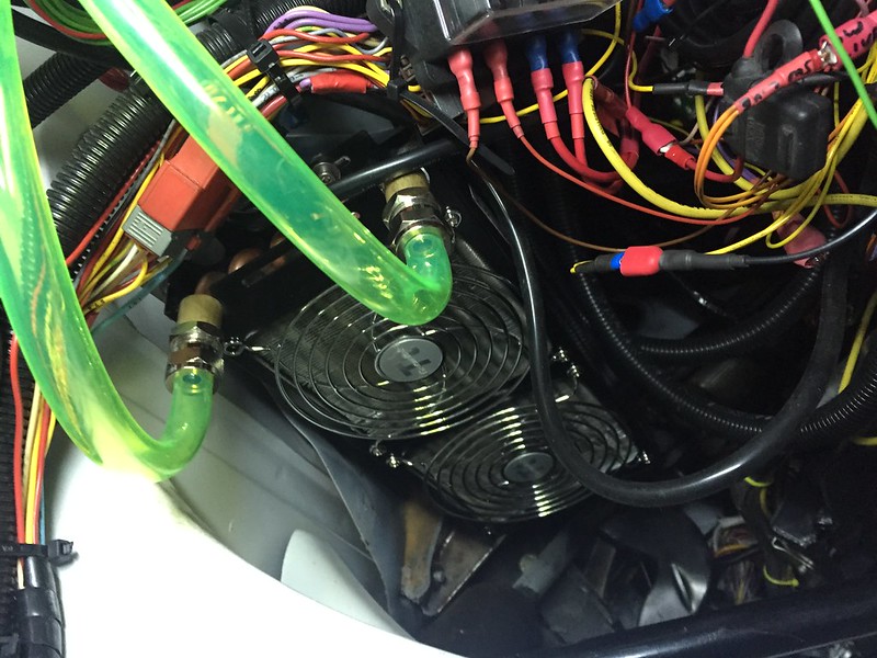
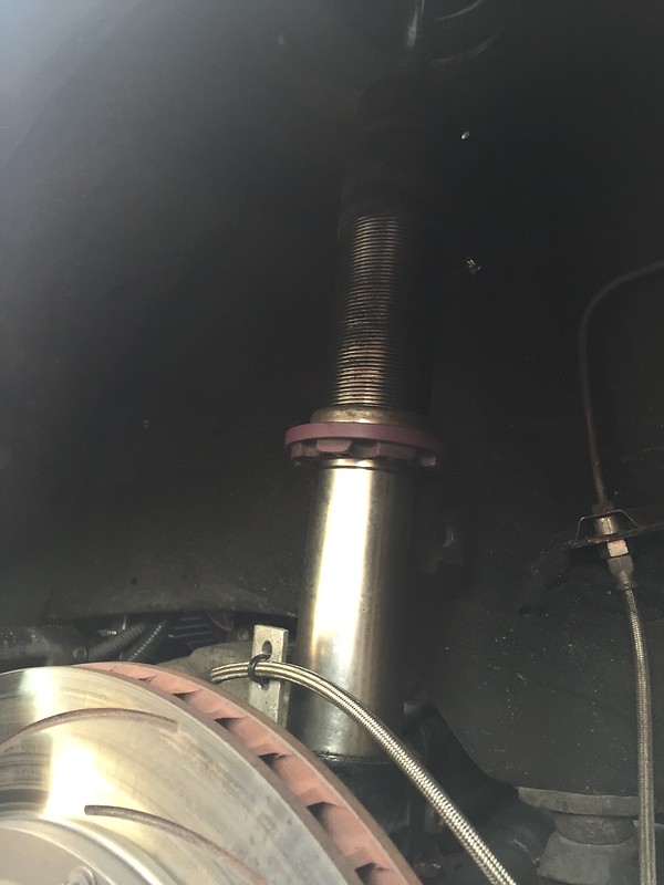
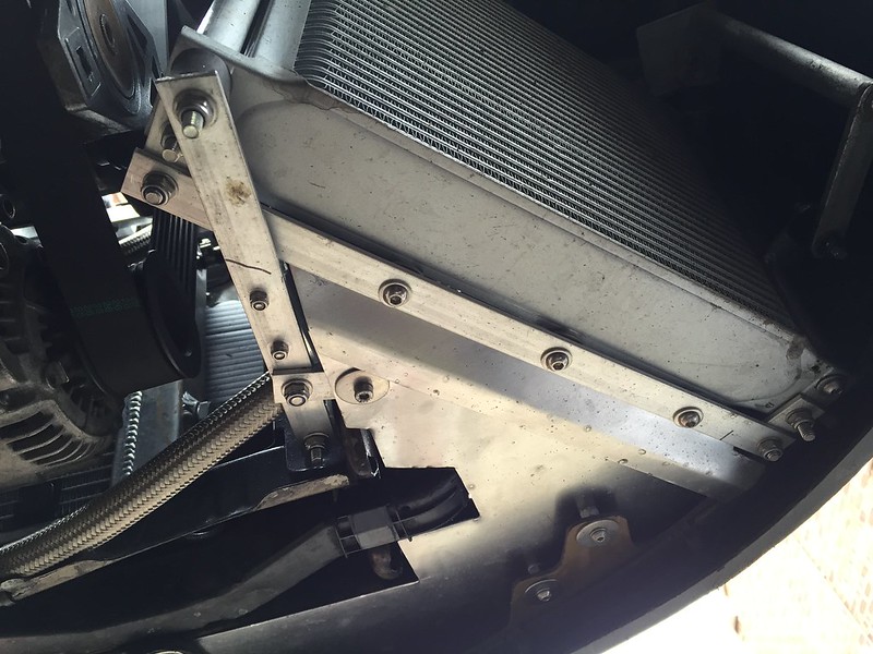
To resolve this i bought a 30 row oil-air cooler and some extra fittings and braided line.
The only place i found where i could mount such a big cooler was infront of the front offside wheel, and even then it has to be at an angle to clear the tyre and bumper.
I also made a shroud for this which basically stops air being able to go underneath the car once it has passed through the grille and foglight opening, the shroud also blocks air being able to go into the engine compartment or above the oil cooler. I didn't get pictures of the shroud as it was always dark by the time i finished working on the car.
The oil now leaves the block and goes straight into the oil-air cooler, then up into the laminova, then to the remote filter then back into the block. The oil and coolant temps seem to be fine with normal driving on the road, although they were the same before i fitted the new cooler. The real test will be next month at Cadwell park, hopefully the oil won't get above 90c with any luck!
One other job i've done is fit a boost gauge. Straight outta max power
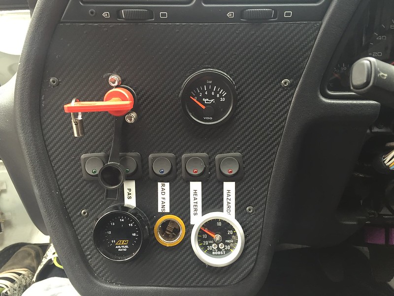 IMG_6798
 by
Steve Count, on Flickr
I wanted it to see whether boost spikes when lifting off the throttle at high speeds, or whether the boost stays higher than normal when ive closed the throttle at high speed, which would mean the dump valve isn't clearing the boost quick enough. I suspect its one of these issues that is causing me to destroy the superchargers and i was hoping this gauge would give me an indication which one is the issue.
Unfortunately, like most bargains i come across on ebay, this doesn't seem to work at all. £7 well spent there then

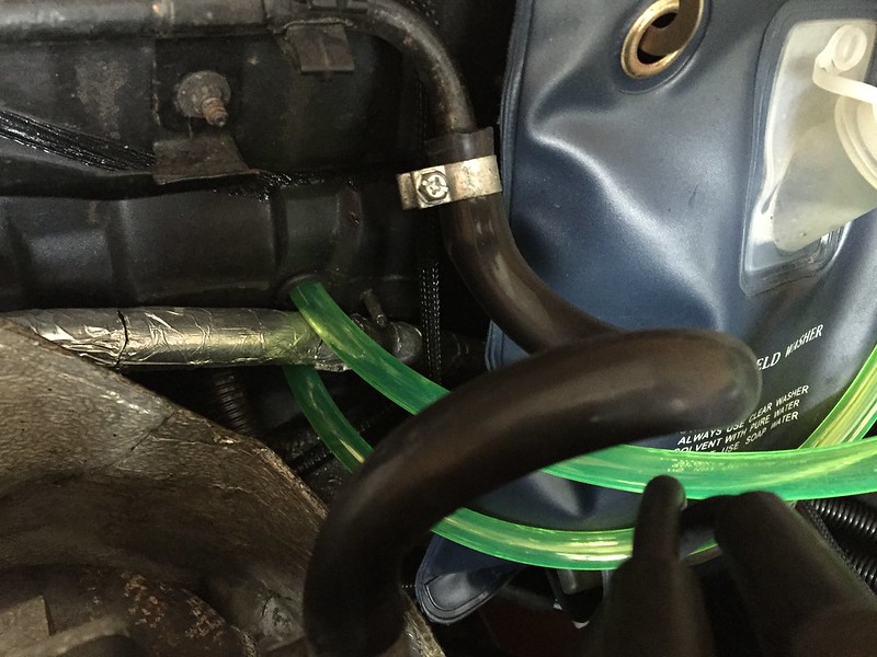
The gauge works a bit when i suck/blow on the hose, so i suspect that its just the vacuum hose is nipped up where i shoved it though the grommet in the bulkhead, as i tried squeezing it through with the wiring loom.
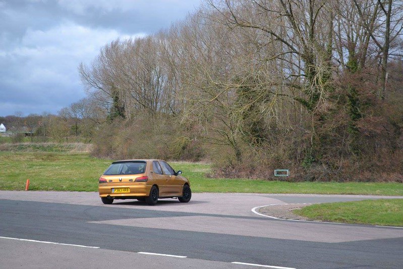
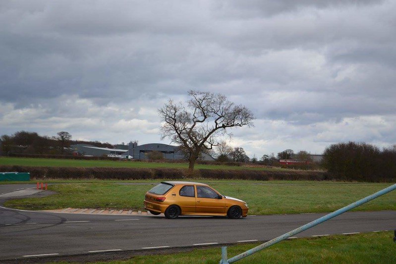
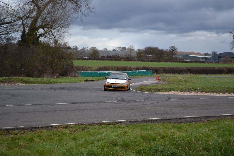
Finally I put everything back together, taxed it and got it out for a drive.
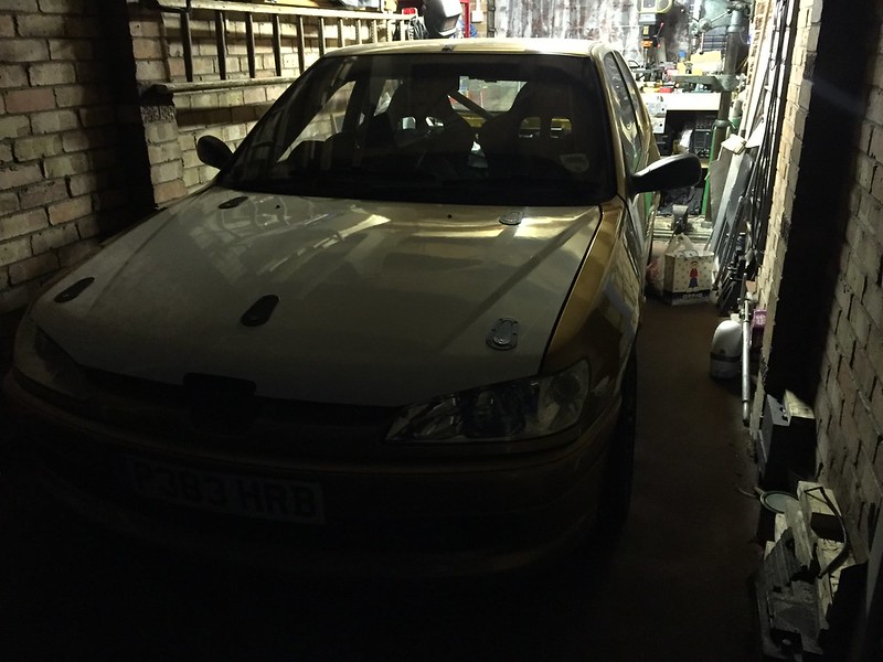 IMG_6801
 by
Steve Count, on Flickr
I'm using one of the superchargers that has had 0.2mm removed from the rotors, and i suspect that it's not creating as much boost as it used to do, which is understandable, its still much quicker than it was n/a and the afr's don't seem too far out so i can live with it for now.
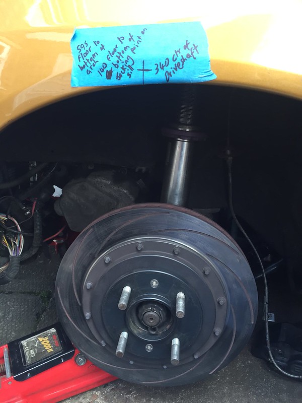
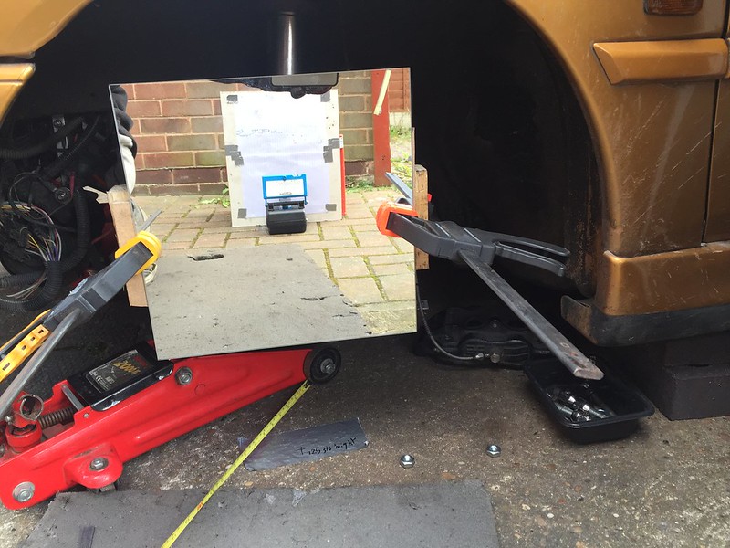
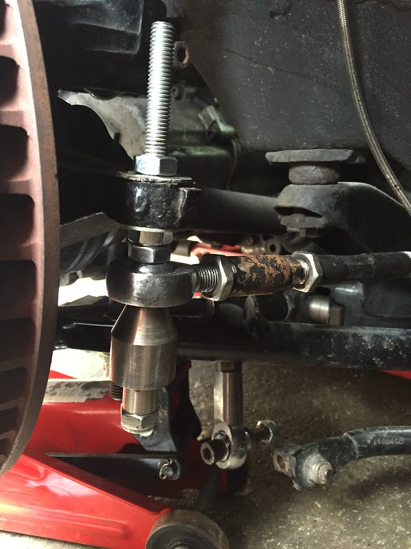
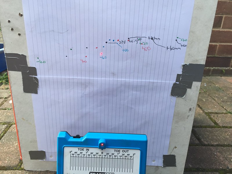
I checked the tracking, it's at 10 minutes toe-in, and also rotated the steering wheel one spline so its a little more like centred when driving in a straight line.
There's one other little update to add, but i'm still waiting on some parts for that, and its non-essential so it can wait a week or two. Hopefully this will now be at the pscuk sprint day at Curborough next monday.

________________________________________
Goldie the track car.


 (and they wonder why they struggle to cool them...)


 Fingers crossed