displaying posts 1 to 25 of 53

Pages (3): [1] 2 3

Author Subject: Technical induction discussion
cwspellowe

Seasoned Pro

Location: Calderbank

Registered: 19 Jul 2009

Posts: 6,496

Status: Offline

Post #1
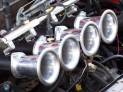
Hi fellas, hoping some of you on here have some insight into the mechanical properties of various induction kits etc, looking for a few pointers.

I'm going to be making my own carbon fibre air box when I get chance, basically reworking the standard airbox to provide better air mass and lower induction temperatures, combined with a bypass valve to counteract the problem of water ingress during winter. It's going to be similar to the ITG Maxogen kits but a hell of a lot cheaper, although i'm considering using one of their filters depending on which shape will provide the best air flow for the design.

Few things -

1. Air flow is at is densest (higher pressure) at the leading edge of the car, right? So the optimal place to have the trumpet for the feed is going to be pretty central to the car?

2. Possible ramming of the air is needed to negate the resistance the filter provides relative to the required air draw of the engine, is that correct? ie. running with no filter would be the optimum for performance with the downside of zero filtration?

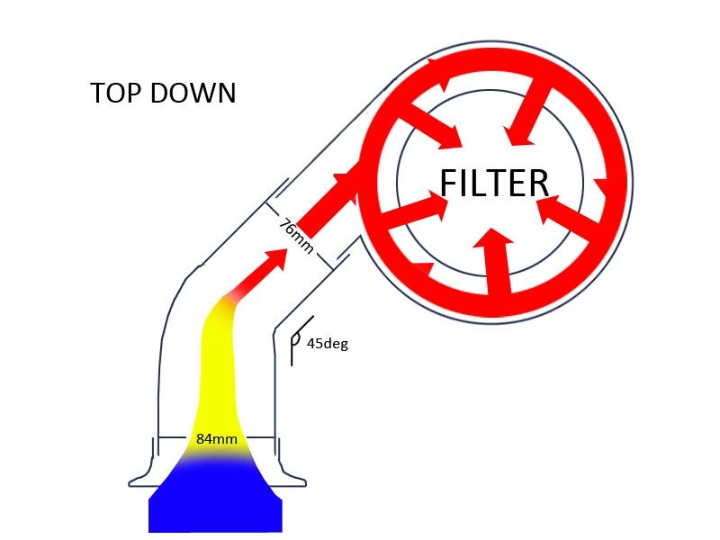
3. Does the shape of the pipework before the filter at all affect the air flow after the filter? ie. would pipework with a lot of bends, or with flexi sections, negatively affect the flow of air? Is the straightest possible path ideal?

4. If you were to have a kind of "swirl pot" for the air, a cylindrical box with air entering to one side at the bottom, what shape of filter would be best, a conical or cylindrical filter?

5. Would having a trumpeted piece on the end of the induction hose have the same effect as trumpets on throttle bodies? What is that exactly? Increasing flow and reducing turbulence? If a flexi section was fitted to it, before the air filter, would it make any difference?

Lots of question still to come, does anyone have any links to this kind of research online anywhere? Motorsports journals etc?

I feel a project coming on Cool

________________________________________

Bye bye Sundance Kid Sad
Posted 8th Jul 2011 at 03:21
mattgti6phase2

Seasoned Pro

Location: inside my 6 abusing the tarmac!!

Registered: 16 Jul 2010

Posts: 2,371

Status: Offline

Post #2
Interesting thread.

Tbh the easiest thing to do would be to replicate what pug have already done. If the induction pipes are too big in diameter then air pressure will be lost in the same way that an engine loses back pressure if the bore is too large ( in the case of N/A engines )

Maybe for the main induction pipe you could create a larger opening e.g 4 inch diameter down to maybe half that to
create greater air pressure.

I'm sure there will be many other opinions so it may be a case of trial and error. Reverting back to how pug have done it is a pretty good way of feeding the engine. The air is squeezed (forced) into the snorkel) under pressure the bends in the system also help this.

I run the standard set up with a cotton filter and modified
snorkel also I got rid of the terrible air gap between the down pipe and the air box by using a stainless steel sleeve this has made it completely air tight. You can feel my setup drawing air on idle then with a twist of throttle you can pretty much Hoover humans up LOL works for me.

Hope this helps.

________________________________________

Team Nile 6 Superman
Team: 40.2 MPG Smile
5 x a 306 owner!
currently abusing type r's in a town near you ™ Wink
I truely live for the 306 ®
Build date: 29th October 1997 Wednesday's car
midweek madness Tee hee
Posted 8th Jul 2011 at 06:18
720puggti

Seasoned Pro

Location: West London

Registered: 18 Jan 2009

Posts: 1,069

Status: Offline

Post #3
Hi Chris,

I just wanted to answer your questiong about "trumpeted" inductions. I'm gonna recall my jet engine knowledge here....

I don't know whether you're seen a jet engine in a test bed, but they too have a "trumpeted" type intake or "bell" type. The reason for this is because the engine is stationery. That type of induction is used to minimise the resistance the airflow encounters as it is sucked into the engine; resistance is along the intakes edges. That's why you have that nice curve or "trumpet" shape.

This is applicable to throttle bodies as they too are stationery. However, for your car a bell type induction is pointless as you're not using it for its correct purpose.

My heads swimming with ideas at the moment, none of which I can coherently put down in this post. When I can manage to put the words in order I'll post again.

Good luck with it though Smile

________________________________________

Deepak Gohil


Posted 9th Jul 2011 at 00:55
cwspellowe

Seasoned Pro

Location: Calderbank

Registered: 19 Jul 2009

Posts: 6,496

Status: Offline

Post #4
Matt, I'm well aware you hate induction kits, you seem to pop up on every thread LOL

Deepak cheers for the input, i'd have thought though that a trumpeted air feed would accelerate the air around it adding to the pressure build up? For the sake of £10 for a trumpet is it not worth trying it?

Basically my idea at the minute is a carbon airbox (possibly a full carbon system if practicality allows..) sat where the standard airbox is. Smooth 90degree elbow to the throttle body. Air feed running out of the side of the airbox, aiming to create a kind of swirl pot, with the feed running through the chassis to the front bumper, as close to the high pressure front as possible. Also thinking of having a larger inlet opening, say 90mm or so, reducing to 76mm at the airbox, as Matt says to accelerate the air and increase air pressure, attempting to negate the resistance of the air filter with the increased pressure.

Materials wise, i can lay the carbon myself and the pipes should be easy to get hold of, just need to start measuring!

Will try and knock up a photoshop of my idea. I'd like to know if anyone has any experience of fluid dynamics and the relative software...

________________________________________

Bye bye Sundance Kid Sad
Posted 9th Jul 2011 at 01:36
welshpug!

Capt Pedantic

Location: Bigend, Wales.

Registered: 27 Mar 2007

Posts: 25,817

Status: Offline

Post #5
I think before you actually make anything, you need to ascertain if there's actually any flaws at all in the standard system.

You need to measure the air pressure at the scoop and the other side of the filter at given engine loads and wind speed, this will give you some idea if you find any improvements anywhere.

________________________________________

need a part number? get on here - http://public.servicebox.peugeot.com

Bring on the Trumpets.

Posted 9th Jul 2011 at 01:42
cwspellowe

Seasoned Pro

Location: Calderbank

Registered: 19 Jul 2009

Posts: 6,496

Status: Offline

Post #6
Duly noted Mei.

Bear in mind this isn't a dissertation or anything, just seeing if I can at least match if not better the carbon enclosed kits you see on the market. It's widely opined that if you get an induction kit, it should be a closed induction system instead of an open filter.

I'm not trying to see if the standard system can be improved, i'm trying to see if the £200 kits can. They say they're model specific but all that means is the neck diameter is correct, they're technically still "universal".

**EDIT i just re-read my opening post, makes it sound like i'm dicking about with the standard airbox. Ignore that.

________________________________________

Bye bye Sundance Kid Sad
Posted 9th Jul 2011 at 01:46
mattgti6phase2

Seasoned Pro

Location: inside my 6 abusing the tarmac!!

Registered: 16 Jul 2010

Posts: 2,371

Status: Offline

Post #7
cwspellowe wrote:
Matt, I'm well aware you hate induction kits, you seem to pop up on every thread LOL.


LOL

Its just based on my opinion. I just think that Peugeot must have spent X amount of money on designing the system which must mean it works.

Now I understand that you just wish to improve the after Market kits I wish you every bit of luck Big grin I've seen your skills in other threads Cool

________________________________________

Team Nile 6 Superman
Team: 40.2 MPG Smile
5 x a 306 owner!
currently abusing type r's in a town near you ™ Wink
I truely live for the 306 ®
Build date: 29th October 1997 Wednesday's car
midweek madness Tee hee
Posted 9th Jul 2011 at 02:44
cwspellowe

Seasoned Pro

Location: Calderbank

Registered: 19 Jul 2009

Posts: 6,496

Status: Offline

Post #8
mattgti6phase2 wrote:
cwspellowe wrote:
Matt, I'm well aware you hate induction kits, you seem to pop up on every thread LOL.


LOL

Its just based on my opinion. I just think that Peugeot must have spent X amount of money on designing the system which must mean it works.

Now I understand that you just wish to improve the after Market kits I wish you every bit of luck Big grin I've seen your skills in other threads Cool


The only skills i possess are

1. Shoot first, ask questions later

and

2. Whack it with hammers of varying sizes

For example I rolled my arches with a rubber mallet and painted my car with no previous painting experience. My results tend to vary.

________________________________________

Bye bye Sundance Kid Sad
Posted 9th Jul 2011 at 02:46
mattgti6phase2

Seasoned Pro

Location: inside my 6 abusing the tarmac!!

Registered: 16 Jul 2010

Posts: 2,371

Status: Offline

Post #9
quote:
The only skills i possess are

2. Whack it with hammers of varying sizes


LOL are you any relation to Jeremy Clarkson? Razz

________________________________________

Team Nile 6 Superman
Team: 40.2 MPG Smile
5 x a 306 owner!
currently abusing type r's in a town near you ™ Wink
I truely live for the 306 ®
Build date: 29th October 1997 Wednesday's car
midweek madness Tee hee
Posted 9th Jul 2011 at 02:51
cwspellowe

Seasoned Pro

Location: Calderbank

Registered: 19 Jul 2009

Posts: 6,496

Status: Offline

Post #10
Only in beer gut unfortunately. Although I was watching TG on Dave last week where they were building the Caterham, I'm a cross between May and Clarkson. I like everything neat and tidy but tools only work when they're making a loud noise Yes

________________________________________

Bye bye Sundance Kid Sad
Posted 9th Jul 2011 at 02:52
mattgti6phase2

Seasoned Pro

Location: inside my 6 abusing the tarmac!!

Registered: 16 Jul 2010

Posts: 2,371

Status: Offline

Post #11
cwspellowe wrote:
Only in beer gut unfortunately. Although I was watching TG on Dave last week where they were building the Caterham, I'm a cross between May and Clarkson. I like everything neat and tidy but tools only work when they're making a loud noise Yes


Laugh my ass off

A tool isn't a tool unless it can make noise!

________________________________________

Team Nile 6 Superman
Team: 40.2 MPG Smile
5 x a 306 owner!
currently abusing type r's in a town near you ™ Wink
I truely live for the 306 ®
Build date: 29th October 1997 Wednesday's car
midweek madness Tee hee
Posted 9th Jul 2011 at 03:04
daveyboy

aka Jim Davey

Location: Southampton

Registered: 01 Oct 2007

Posts: 8,648

Status: Offline

Post #12
Air flows fastest in a straight line and you will see a pressure drop with every bend. I would concentrate on three things.

1. Getting air to the TB in the straightset line possible.

2. Using the best but least restrictive filter.

3. Keeping heat transfer from the hot engine bay out of the inlet charge.

The first is relatively easy to do if you don't mind moving a few things around in the bay such as the battery. A square carbon air-box (BTCC style, behind the passenger side headlight) with a feed fro the wheel arch should give a good result, a straight run can then come from the side of the box straight to the TB. Place the panel filter near the bottom of the box this should give the airflow some space above to recover from the turbulence and head in a nice straight line to the TB. As far as pipe diametwers go, I would'nt deviate much from Peugeots standard size (Unless you are making other mods that will require more airflow) as what you have to remember is that the biggest restriction to flow will be the engine itself. Does'nt matter how much air you try to feed it with, the controlling section will be the TB, the Plenum, runners and ports. At some point the maximum flow potential of the standart inlet tract will be exceeded and the engine just won't make use of anymore air unless you modify it as well. You will see gains up to a point though, probably a fair bit will come from a well insulated induction kit keeping the inlet charge temps down. But to make the most of more air coming in, the ECU will have to provide more fuel as more air with the same fuel means leaner running and less power.

________________________________________

R H Davey Welding Supplies. I sell new and used welding equipment in the Hampshire area. I take on welding jobs in the evenings, ally casting repairs are one of my specialities but I can weld pretty much anything. PM me with your requirements.

Some of my services: (See my for sale threads)
Engine mount/chassis repair
Solid Beam Mounts BACK IN PRODUCTION
Harness bars
Posted 9th Jul 2011 at 03:05
welshpug!

Capt Pedantic

Location: Bigend, Wales.

Registered: 27 Mar 2007

Posts: 25,817

Status: Offline

Post #13
along a similar theory to the straight lines, the group N PTS (GREEN) induction kit for these cars is a straight pipe and places a fairly large filter right where the ABS pump goes, i.e they didn't have ABS LOL

probably not ideal without any ducting or boxing in, but that didn't seem to worry PTS.

________________________________________

need a part number? get on here - http://public.servicebox.peugeot.com

Bring on the Trumpets.

Posted 9th Jul 2011 at 03:10
cwspellowe

Seasoned Pro

Location: Calderbank

Registered: 19 Jul 2009

Posts: 6,496

Status: Offline

Post #14
daveyboy wrote:
Air flows fastest in a straight line and you will see a pressure drop with every bend. I would concentrate on three things.

1. Getting air to the TB in the straightset line possible.

2. Using the best but least restrictive filter.

3. Keeping heat transfer from the hot engine bay out of the inlet charge.

The first is relatively easy to do if you don't mind moving a few things around in the bay such as the battery. A square carbon air-box (BTCC style, behind the passenger side headlight) with a feed fro the wheel arch should give a good result, a straight run can then come from the side of the box straight to the TB. Place the panel filter near the bottom of the box this should give the airflow some space above to recover from the turbulence and head in a nice straight line to the TB. As far as pipe diametwers go, I would'nt deviate much from Peugeots standard size (Unless you are making other mods that will require more airflow) as what you have to remember is that the biggest restriction to flow will be the engine itself. Does'nt matter how much air you try to feed it with, the controlling section will be the TB, the Plenum, runners and ports. At some point the maximum flow potential of the standart inlet tract will be exceeded and the engine just won't make use of anymore air unless you modify it as well. You will see gains up to a point though, probably a fair bit will come from a well insulated induction kit keeping the inlet charge temps down. But to make the most of more air coming in, the ECU will have to provide more fuel as more air with the same fuel means leaner running and less power.


Good lad Thumbs up

Problem with that is the rad top hose is blocking the route to the inner wing. Also have the ABS stuff there too so would be a PITA to fit a box there and it definitely wouldn't fit behind the bumper.

I know the throttle body will ultimately limit the airflow. That's a 76mm OD (about 73mm ID?) so wouldn't go and wider than that between it and the filter. I am thinking of a trumpeted 90mm to 76mm feed from the front bumper leading to the bottom of an airbox just in front of the the gearbox, then a smooth constant diameter pipe from the filter to the tb. My uneducated theory being that the reducer would increase air pressure in the air box and possibly increase throttle response as there's less partial vacuum when applying load to the engine?

I'm trying to keep the filter - tb pipe as long as possible by getting the filter as low as possible, as you say leaving more space to settle the turbulence. Looking at a side entry box as one of the problems with the BMC's and Vipers is they are bottom fed and cold feeds like to get ripped off them.

________________________________________

Bye bye Sundance Kid Sad
Posted 9th Jul 2011 at 03:14
daveyboy

aka Jim Davey

Location: Southampton

Registered: 01 Oct 2007

Posts: 8,648

Status: Offline

Post #15
welshpug! wrote:
along a similar theory to the straight lines, the group N PTS (GREEN) induction kit for these cars is a straight pipe and places a fairly large filter right where the ABS pump goes, i.e they didn't have ABS LOL

probably not ideal without any ducting or boxing in, but that didn't seem to worry PTS.


Forgot about ABS, mine has been gutted beyont all recognition now and I tenfd to forget what is crammed into a standard engine bay. Basicly its a compromise is'nt it? In order to get the best of something, you have to be prepared to make a fair few changes to what is already there. Question is, will all your effort lead to a result that warrants the time?

________________________________________

R H Davey Welding Supplies. I sell new and used welding equipment in the Hampshire area. I take on welding jobs in the evenings, ally casting repairs are one of my specialities but I can weld pretty much anything. PM me with your requirements.

Some of my services: (See my for sale threads)
Engine mount/chassis repair
Solid Beam Mounts BACK IN PRODUCTION
Harness bars
Posted 9th Jul 2011 at 03:14
cwspellowe

Seasoned Pro

Location: Calderbank

Registered: 19 Jul 2009

Posts: 6,496

Status: Offline

Post #16
I have plenty of time on my hands at the minute tbh. Work from home so don't need the car on the road as much, can happily pop it up on stands for a couple of days and play about

________________________________________

Bye bye Sundance Kid Sad
Posted 9th Jul 2011 at 03:16
daveyboy

aka Jim Davey

Location: Southampton

Registered: 01 Oct 2007

Posts: 8,648

Status: Offline

Post #17
A reducer will only increase pressure locally and just after, beyond that there will be a pressure loss. Air does'nt like sudden changes in section, the ideal angle for any kind of reducer if you decide you need one is a 15 degree included angle. Forget tryiing to force air into the engine using wind or reducers, think of the engine a powerful vaccum cleaner, if you can allow it to suck in air in the smoothest, least restrictive way possble you are onto a winner.

________________________________________

R H Davey Welding Supplies. I sell new and used welding equipment in the Hampshire area. I take on welding jobs in the evenings, ally casting repairs are one of my specialities but I can weld pretty much anything. PM me with your requirements.

Some of my services: (See my for sale threads)
Engine mount/chassis repair
Solid Beam Mounts BACK IN PRODUCTION
Harness bars
Posted 9th Jul 2011 at 03:20
cwspellowe

Seasoned Pro

Location: Calderbank

Registered: 19 Jul 2009

Posts: 6,496

Status: Offline

Post #18
AYe i'm not trying to benefit from rammed air, iirc that's only effective at 150mph or something?

I'm meaning to increase pressure in the airbox. So when the engine DOES increase load it doesn't cause any kind of lag, however minor, caused by the slight drop in pressure from sucking more air in. My theory being the more air available at the filter, the more air can be drawn in by the engine as required..?

Imagine a stationary car, press the throttle and the local air pressure at the filter will drop as air is drawn in. If the pressure there is higher than atmospheric, flow will increase when air is drawn due to the higher air pressure difference between pre and post filter. A bit like the leaf blower supercharger but a lot less pikey. Also the reducer on a 45 or 90 degree bend on a cold air feed will hopefully negate the flow lost by the bend itself.

The feed i'm planning is going to be one bend at most from central front bumper to airbox

________________________________________

Bye bye Sundance Kid Sad
Posted 9th Jul 2011 at 03:34
daveyboy

aka Jim Davey

Location: Southampton

Registered: 01 Oct 2007

Posts: 8,648

Status: Offline

Post #19
As long as your cold air feed pipe is of a sufficient size that it's flow outperforms the exit from the airbox to the TB then you won't have to worry about pressure drops and reducers and such. I expect you will find the best performing filter to be a panel type, not as sexy as a nice cone, but far more surface area usually for a given size. You are going to struggle to increase pressure to the inlet side of the filter without the unwanted side effect of reducing air speed and mass flow.

________________________________________

R H Davey Welding Supplies. I sell new and used welding equipment in the Hampshire area. I take on welding jobs in the evenings, ally casting repairs are one of my specialities but I can weld pretty much anything. PM me with your requirements.

Some of my services: (See my for sale threads)
Engine mount/chassis repair
Solid Beam Mounts BACK IN PRODUCTION
Harness bars
Posted 9th Jul 2011 at 03:49
cwspellowe

Seasoned Pro

Location: Calderbank

Registered: 19 Jul 2009

Posts: 6,496

Status: Offline

Post #20
Yes noted

Not sure how I would benefit from focusing on that, as long as the airbox can get a good enough flow of air and the filter has a good compromise of filtration and flow rate.

Thinking of throwing in an AEM water bypass valve upstream of the filter too. The box will be more rigidly mounted than a Viper with a cold air feed so would be a PITA come wet weather.

________________________________________

Bye bye Sundance Kid Sad
Posted 9th Jul 2011 at 03:51
daveyboy

aka Jim Davey

Location: Southampton

Registered: 01 Oct 2007

Posts: 8,648

Status: Offline

Post #21
Good idea the AEM valve, although an oil breather style filter (Piper do one with a 30mm neck) mounted near the top of the airbox would probably kill of any chance of the engine syhoning up water. Is there any way you can collect your air from behind the front of the inner wheel liner, with saty some ducted air coming from the fog light hole? It would be perfectly placed to avoud bieng ripped off by speed bumops and suckibg in water from puddles etc.

________________________________________

R H Davey Welding Supplies. I sell new and used welding equipment in the Hampshire area. I take on welding jobs in the evenings, ally casting repairs are one of my specialities but I can weld pretty much anything. PM me with your requirements.

Some of my services: (See my for sale threads)
Engine mount/chassis repair
Solid Beam Mounts BACK IN PRODUCTION
Harness bars
Posted 9th Jul 2011 at 04:00
cwspellowe

Seasoned Pro

Location: Calderbank

Registered: 19 Jul 2009

Posts: 6,496

Status: Offline

Post #22
I have a better idea than that. You seen the guy in Germany building an SC Rallye? He's squeezed his IC pipework through the chassis by the rad, i'm thinking similar for the cold air feed. Straight from the front with the highest air pressure, 45 degree bend to airbox where standard airbox is. Am drawing it up now so you can see

________________________________________

Bye bye Sundance Kid Sad
Posted 9th Jul 2011 at 04:02
cwspellowe

Seasoned Pro

Location: Calderbank

Registered: 19 Jul 2009

Posts: 6,496

Status: Offline

Post #23
Here


The idea being a nice simple rigid feed to channel air to the airbox. Will need to research filter size to work out box size on the feed side of the filter so air pressure in the box doesn't drop too much.

Thinking of a conical base to aid air circulation too, to create a kind of vortex.

________________________________________

Bye bye Sundance Kid Sad
Posted 9th Jul 2011 at 04:22
cwspellowe

Seasoned Pro

Location: Calderbank

Registered: 19 Jul 2009

Posts: 6,496

Status: Offline

Post #24
And a crap one from the front, you get the idea

________________________________________

Bye bye Sundance Kid Sad
Posted 9th Jul 2011 at 04:37
gilesy

Seasoned Pro

Location: Greenwich - in that London

Registered: 03 Apr 2006

Posts: 5,133

Status: Offline

Post #25
Whistle

Posted 9th Jul 2011 at 04:52

Pages (3): [1] 2 3

All times are GMT. The time is now 12:44

The Peugeot GTi-6 & Rallye Owners Club - ©2024 all rights reserved.

Please Note: The views and opinions found herein are those of individuals, and not of The Peugeot 306 GTi-6 & Rallye Owners Club or any individuals involved.
No responsibility is taken or assumed for any comments or statements made on, or in relation to, this website. Please see our updated privacy policy.